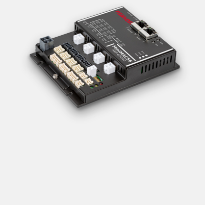
For more information, please contact our sales support with the request form. Thank you
Specifications
| Product | |
| Weight | 500 g |
| Motor | |
| DC motors up to | 528 W |
| EC motors up to | 528 W |
| Sensor | |
| Without sensor (DC motors) | Yes |
| Digital incremental encoder (2-channel, single-ended) | Yes |
| Digital incremental encoder (2-channel, differential) | Yes |
| Digital incremental encoder (3-channel, differential) | Yes |
| Digital Hall sensors (EC motors) | Yes |
| Absolute encoder (SSI) | Yes |
| Analog incremental encoder (2-channel, differential) | Yes |
| Operating modes | |
| Current controller | yes (torque) |
| Speed controller (closed loop) | Yes |
| Position controller | Yes |
| Electrical data | |
| Operating voltage Vcc (min.) | 10 V |
| Operating voltage Vcc (max.) | 60 V |
| Logic supply voltage Vc (min.) | 18 V |
| Logic supply voltage Vc (max.) | 30 V |
| Max. output voltage (factor * Vcc) | 0.88 |
| Max. output current Imax | 30 A |
| Max. time of peak output current Imax | 5 s |
| Continuous output current Icont | 10 A |
| PWM clock frequency of power stage | 48 kHz |
| Sampling rate PI current controller | 24 kHz |
| Sampling rate PI speed controller | 8 kHz |
| Sampling rate PID positioning controller | 1 kHz |
| Max. efficiency | 98 % |
| Max. speed (DC) | 50000 rpm |
| Max. speed (EC; 1 pole pair) block commutation | 50000 rpm |
| Max. speed (EC; 1 pole pair) sinusoidal commutation | 50000 rpm |
| Inputs | |
| Hall sensor signals | H1, H2, H3 |
| Encoder signals | A, A\, B, B\, I, I\ |
| Max. encoder input frequency | 6.2 MHz |
| Sensor signals | Clock, Data |
| Digital inputs | 16 |
| Functionality of digital inputs | free programmable |
| Analog inputs | 4 |
| Resolution, range, circuit | 12-bit, 0…+10V |
| Functionality of analog inputs | free programmable |
| Functionality of the DIP switch | Node ID, CAN Bus Termination |
| Outputs | |
| Digital outputs | 8 |
| Functionality of digital outputs | free programmable |
| Voltage outputs | |
| Hall sensor supply voltage | +5V DC |
| Encoder supply voltage | +5V DC, max. 200mA |
| Sensor supply voltage | +5V DC, max. 200mA |
| Interface | |
| USB (full speed) | yes |
| CAN | Yes |
| CANopen | Master / Slave |
| CANopen application layer | CiA 301 |
| CANopen profiles motion control | CiA 402 |
| EtherCAT | EtherCAT Slave |
| CoE (CAN application layer over EtherCAT) | yes |
| Distributed Clocks Support | Yes |
| Variable PDO mapping | Yes |
| Display | |
| Status indicator "Ready" | green and yellow LED |
| Status indicator "Error" | red LED |
| Status indicator of communication interface | yes |
| Protective functions | |
| Protective functions | Current limitatino, over current, over temperature, under voaltage, over voltage, free programmable |
| Ambient conditions | |
| Temperature – Operation (min.) | -30 °C |
| Temperature – Operation (max.) | 50 °C |
| Temperature – Extended Range | +50…+70 °C, if the PCB temperature exceeds +80 °C, the power stage will be switched off |
| Temperature – Storage (min.) | -30 °C |
| Temperature – Storage (max.) | 85 °C |
| Humidity (non-condensing) (min.) | 5 % |
| Humidity (non-condensing) (max.) | 90 % |
| Mechanical data | |
| Weight | 370 g |
| Dimension (length) | 109.5 mm |
| Dimension (width) | 140.5 mm |
| Dimension (height) | 34.2 mm |
| Mounting | see Referenz Manual |
| Software | |
| Installation program | ApossIDE |
| Graphical User Interface | ApossIDE |
| Operating system | Windows 11,10, 7 |
| Windows DLL for PC | 32-/64-bit |
| Linux Shared Object Library | X86 32-/64-bit |
| CAN Interfaces | USB CAN Adapter |
| Programming example | ApossC_SDK, MS Visual C#, MS Visual C++ |
| Functions | |
| Velocity mode | Yes |
| Current mode | Yes |
| Master Encoder Mode | Yes |
| Analog set value | Yes |
| Path generator with sinusoidal/trapezoidal profiles | Yes |
| Position Control Feed Forward | Yes |
| Velocity Control (Feed Forward) | Yes |
| Position Marker / Touch Probe | Yes |
| Quickstop | Yes |
| Enable | Yes |
| Position Compare | Yes |
| Control of holding brakes | Yes |
