How to configure an EPOS4 Positioning Controller using EPOS Studio
By Amir Janjua, Technical Engineer, maxon UKI
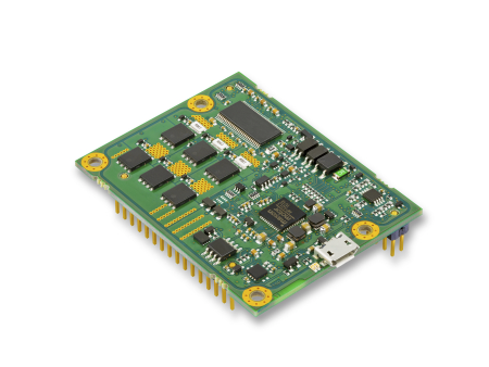
The maxon EPOS4 digital positioning controller is the next generation of powerful CANopen controllers. maxon’s EPOS Studio software is used to configure initial parameters and set up drive systems for commissioning. The following is a guide on configuring the EPOS4 to suit your motor and application by using the EPOS Studio graphical user interface (GUI) interface.
EPOS Studio Download
Before you receive your EPOS4 it is a good idea to download the EPOS Studio to establish some familiarity with the software. The link below goes to the EPOS homepage where the download link for the EPOS Studio can be found towards the bottom of the page:
Creating a New Project
When the EPOS Studio has been downloaded and installed, the initial screen gives the option to create a new project based on the range of EPOS models.
Here you can select which EPOS you are using. The latest EPOS version is the EPOS4 and this is suitable for most applications.
There are two ways of starting your project, choosing “EPOS4 Project”, takes you to the next screen where you can name your project and save it. If you opt for this method, the EPOS Studio will assume you are connecting via USB.
Alternatively, if you choose “Create New Project” you can name your project and save it. On the next screen confirm the EPOS being used and click the “>>” button. Select the communication interface you will be using:
• RS232
• CANopen
• USB
• EtherCAT
NOTE: If you are using a CAN interface to communicate to your PC, the EPOS Command Library 9.2.1.1 shows interfaces and drivers that have been tested by maxon.
The last screen is where you select the device in your network, choose EPOS4 to complete the “Network Structure”.
Once this initial configuration of controller and communication has been completed, you will see one of two options on the left-hand navigation pane, under the “Communication” window.
If you have your EPOS4 connected to your PC, your communication tree will be all clear and there will no red crosses. If your EPOS4 is not connected there will be red crosses over the communication interface and the chosen EPOS.
NOTE: For the EPOS Studio to recognise the EPOS4, the controller MUST be powered on with an external supply. USB supply is not enough even for configuration. To calculate your power requirements from your power supply, please see the “EPOS4 Hardware Reference” where you can find an equation with variables such as torque requirements, speed requirements and motor data.
Start Up Wizard
Within the navigation pane, there is a section named “Wizards” under this there are various step by step options.
Firstly, the “Start-up Wizard” should be used. This is where you can define the motor and sensor combination, its parameters and the system limitations, as well as analog and digital I/O selection.
Safety Instructions
Please read the safety instructions carefully and confirm you have read and understood. Following this you will be asked to define your motor parameters.
Motor Data
These values can all be found on the maxon website
( www.maxongroup.co.uk/maxon/view/content/overview-dc-motor) or in the catalogue ( www.maxongroup.co.uk/maxon/view/content/catalog_request). If you are unsure, please get in touch and we can help on +44 (0)1189 733337.
It is important to make sure the information filled out is correct. The motor will be at risk of overload if the nominal current and thermal time constant winding is incorrect and overestimated. If the motor is overloaded for too long there will be irreversible damage to the internal winding.
The maximum speed can be found on line 23 of the motor data sheet. This is not to be confused with nominal speed or no-load speed, as these are defined assuming nominal voltage is applied to the motor. The EPOS4 will supply the required voltage to the motor based on the speed requirement and the torque being applied, assuming there is no limitation from the power supply.
It is important to understand how the max speed available from the EPOS4 varies with the number of pole pairs of the motor. As standard, all EPOS4 models offer a max speed of 50000 rpm when running in sinusoidal commutation, and 100000 rpm when running in block commutation, this is for a motor with 1 pole pair. As the number of pole pair increases, the maximum speed decreases at the same rate, to calculate divide the max speed (based on which method of commutation you use) by the number of pole pairs to calculate the maximum speed for your motor. For example, running a motor with 4 pole pairs using block commutation results in a max speed of 25000 rpm.
Gearhead
Once the motor section has been completed, there is an option to configure a gearbox if there is one on the motor, if not, you can skip this section.
If there is a gearhead on the front of the motor for maximum accuracy it is important to configure the gearbox as an absolute ratio rather than a x:1 format as this has been simplified. The absolute reduction can be found on the gearbox data sheet, along with the maximum continuous input speed which is defined to prevent any damage to the gearbox and the teeth of the individual gears.
Sensors
With the EPOS4, closed loop feedback is necessary, this may be an encoder on a DC motor or even hall sensors on an EC (brushless DC motor). The sensor should be chosen based on the feedback resolution required. Hall sensors offer 6 pulses per electrical turn (pole pair) so is not sufficient in most applications which require position control.
Hall Sensors
On the sensors section of the Start-up Wizard, there is an option to configure hall sensors (for brushless motors). If you are using a maxon motor select “maxon” polarity, however, if you are using a third-party motor you would need to confirm the sequence of the hall sensors with respect to the windings. there is an option to configure the hall sensors as “inverted” which simply shifts all hall sensor phases by 180 degrees. Connectors X5 and X6 can both be configured as sensors (X5 must be a Digital Incremental Encoder), giving the option of running in Dual-Loop Mode which means the EPOS4 takes feedback from the sensor on the motor and an additional sensor anywhere else within the system, typically on the load. This is very useful for applications where there may be excessive backlash or torsional elasticity which must be accounted for. For more information on Dual-Loop Encoder Mode, see EPOS4 Application Notes, section 9.
Encoder
An encoder can be configured for connector X5. This can be mounted on either the motor shaft or the load, however, if there is not an encoder present on the motor, there is only the option to operate the motor using block commutation (for brushless motors). If a brushed DC motor is in use one form of feedback is required and that can be on the load. It Is always recommended to use encoders with differential signals as a method of protection against electrical interference, as well as using 3 channel encoders.
Sensor
If a secondary encoder is in use, or if there is only one form of feedback and it is not a digital incremental encoder, then this must be configured through connector X6. See hardware reference for wiring information. Additional sensors available are digital incremental encoder 2 (mounted to load), Analog Incremental Encoder (on motor or on load) and SSI Absolute Encoder (on motor or on load).
The EPOS4 Hardware Reference for the relevant EPOS4 has information on the specification of the feedback sensor connectors which the sensors must conform to, such as power requirements and the EPOS4 Firmware Specification has information on the data of the sensors, such as SSI Data Rate, number of data bits and other limitations. This should be analysed prior to selecting the sensor to be used for the application.
Commutation
If a brushed DC motor is in use there is no need to configure the commutation method, however, if a brushless motor is in use, there are two options available depending on the feedback which has been configured. Providing there is an additional sensor, as well as the hall sensors mounted to the motor shaft, the motor can operate using sinusoidal commutation. If the application requires smooth control, especially at low speeds, then sinusoidal commutation is recommended, along with a high resolution sensor. If there is only one encoder, and it is mounted to the load (main encoder), then there is only the option to select block commutation.
Regulation
The next section within the Start-up Wizard is Regulation. This is where the control loop structure can be defined with regards to current, velocity and position.
Velocity
There are two options with regards to the velocity control loop, one of which is low-pass filter and the other is observer. Detailed information can be found in the EPOS4 Application Notes, section 2.6.
In short, observer is typically used if there is a low resolution sensor in use, and if the mechanical parameters are consistent. For example if the load applied to the motor does not fluctuate. Low-pass filter is typically used if a high resolution encoder is available.
Position
Depending on the feedback sensors which have been configured, there is the option for either PID position controller if one encoder is available, or dual-loop position controller. This is if there are two encoders available, one on the motor and the other on the load. Dual-loop is typically used when high position accuracy is required. The EPOS4 Application Notes, section 9, goes into further detail about dual-loop position control.
The final step within the regulation section is defining the main sensor within the system. This is typically the encoder mounted on the motor. Values such as velocity and position are derived from the main sensor, also a holding brake output works based on information from the main sensor.
Units
Within the EPOS Studio there are limited options in terms of defining units. There is only the option to define the unit for velocity. As standard this is in revolutions/min however, it can be changed all the way down to 0.000001 rpm. Each unit option has its own value which can be defined in the Object Dictionary of the EPOS4. These values, along with values and index notations for other variables, can be found in the EPOS4 Firmware Specification.
Limits
The limits section is where parameters are defined as a safety function for the entire system, not just the motor.
Maximum Output Current
maxon motors can be overloaded beyond their nominal torque for a duration that corresponds with the thermal time constant winding. As these values have been defined an output current limit can be configured and it can be higher than the maximum continuous current. This is typical in applications where there is a high acceleration rate or if there is a frequent spike in torque demand from the motor. The maximum output current limit should be less than the short term peak current provided from the controller, and also should be less than the current available from the power supply. If a gearhead is in use the maximum current should fall in line with the maximum continuous torque of the gearhead. The torque constant, which can be found on the motor data sheet, can be used to determine the maximum output current based on the maximum output torque.
Maximum Acceleration
The default value for the maximum acceleration is set at 4294967295 rpm/s as standard. This should be set according to your system in order to avoid mechanical damage and overcurrent issues. It is important to know that the acceleration object is not used in certain operating modes (Cyclic Synchronous Torque, Cyclic Synchronous Velocity and Cyclic Synchronous Mode) as the trajectory path for these modes is defined by the master system.
Maximum Profile Velocity
The maximum profile velocity should consider the following:
• Maximum gearbox input speed
• Supply voltage
• Voltage rating of EPOS4
• Max encoder input frequency
Following Error Window
The Following Error is defined as the maximum allowed difference between the actual position and demand position. If this value has been exceeded, a following value error (0x6065) will be triggered.
There are various factors that influence the following error value. Typically, it comes down to the final load and the permissible motion it can follow. If there is a high ratio gearhead used, the following error can be increased, and also the resolution of the feedback sensor will dictate the magnitude of the error. A low following error value can be entered if a high resolution encoder is used. Typically, one motor turn is sufficient (encoder resolution * 4).
Software Position Limit
There is also the choice to implement a software position limit, meaning the motor can only operate between two points. If this value is exceeded, a software position error is triggered.
Device Control
The device control is where the EPOS4 is configured to perform certain actions based on the given conditions.
Actions
The following are actions that can be configured according to certain conditions:
• Disable Drive Function: Power stage is disabled, drive will slow down according to friction within the system.
• Slow Down on Deceleration: Drive will slow down according to pre-defined deceleration rate.
• Slow Down on Quick Stop Deceleration: Drive will slow down according to pre-defined quick stop deceleration rate, typically higher than deceleration rate.
Profile Deceleration
The profile deceleration is pre-defined and is used in various operating modes except for the cyclic synchronous modes (CSV, CST, CSP).
Quick Stop Deceleration
The quick stop deceleration is also a pre-defined value. It is configured as a digital input meaning it can be used in all applications. The quick stop deceleration value is typically a lot higher than the profile deceleration rate, however, it is important the power supply is able to deal with such a high rate. When a high load is brought to a halt at a quick rate, there is reversed energy which goes back through the system. This cannot be stored in the EPOS so it must go back through to the power supply. If this is not possible there are various options:
• Decrease quick stop rate
• Increase power supply available
• Implement capacitor within the system
• Implement a maxon shunt regulator (Part number 235811 or 309687)
Standstill Window and Time
Within the device control there is also the possibility to configure the “standstill” window and corresponding time. This is useful if there is a holding brake in use that is configured as a digital output in order to coordinate when the brake becomes active, as this must be when the motor has reached a halt.
It is important that the window is not too high, as it may not be a good indicator of whether the motor is truly at the 0 rpm mark.
Digital Inputs
The EPOS4 can take up to 8 digital inputs, 4 of which being standard and the remaining 4 being high speed digital inputs. The specification for these can be found under the relevant EPOS4 Hardware Reference, including information regarding the maximum input voltage.
Typically, the following are configured as digital inputs:
• Positive Limit Switch: Limit switch when motor is rotating in one direction
• Negative Limit Switch: Limit switch when motor is rotating in other direction
• Drive Enable
• Quick Stop: As mentioned earlier in this document
A home switch can also be configured however it is dependant on which homing mode is chosen, the following can be triggered by a digital input:
• Home Switch Positive Speed
• Home Switch Negative Speed
• Home Switch Positive Speed & Index
• Home Switch Negative Speed & Index
Digital Outputs
The EPOS4 has 3 available digital outputs, 1 of which being a high speed digital output.
Digital Outputs 1 and 2 have an open drain circuit and an internal pull up resistor with a diode bringing the voltage up to 5.45 VDC.
One common digital output which is configured is a motor holding brake.
When configuring a holding brake the rise time and fall time are defined by the user, as standard this is 10ms however the range is 0-5000. It is important that the brake is triggered AFTER the standstill window has been reached by the motor.
Analog Outputs
Using the current firmware (0x0150), the analog outputs can only be configured with general purpose functionality.
If you require help or require further information on any maxon controllers or the EPOS studio software please contact us on +44 (0)1189 733337 or sales.uk@maxongroup.com .
© 2019 by maxon UKI
Back to the news overview


